· Dinesh, Lohitashwa · 2 min read
Three-Level PCB Design for Advanced Wheel Control System
This advanced robotic system features a sophisticated two-tier power management architecture designed to efficiently distribute power from a 24V battery source to multiple subsystems. The design incorporates strategic buck converter placement to ensure optimal voltage regulation and independent control of various robotic components.
We developed an innovative three-level PCB architecture specifically designed for a sophisticated wheel control system featuring independent management of rear, middle, and front wheel assemblies. This multi-layered approach ensures optimal performance, signal integrity, and thermal management across all wheel control circuits.
PCB Level Configuration
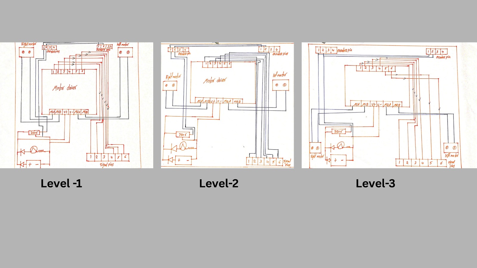
Level 1 is dedicated to back wheel control, incorporating all necessary motor driver circuits, power management components, and signal conditioning elements required for precise rear wheel operation. Level 2 serves as the control hub for the middle wheels, featuring integrated circuits that manage the central wheel assembly’s speed, torque, and directional control. Level 3 handles front wheel management, containing specialized circuitry designed to control steering and front wheel dynamics.
Component Integration Strategy
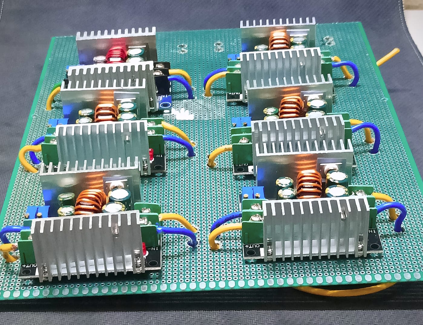
All electronic components are directly integrated onto their respective PCB levels, eliminating external wiring harnesses and reducing potential failure points. The system establishes direct connections to motors and encoders, ensuring minimal signal loss and maximum control precision while maintaining robust electrical isolation between wheel systems.
Signal Architecture and Microcontroller Interface
The PCB signal pins connect directly to a Teensy microcontroller, which serves as the central processing unit for coordinating all three wheel control levels. This direct connection approach eliminates intermediate connectors and provides high-speed communication between the control levels and the main processor, ensuring synchronized operation across all wheel assemblies.
Design Advantages
This three-level PCB architecture provides superior electromagnetic interference (EMI) isolation between wheel control circuits, enhanced thermal management through distributed heat dissipation, and simplified troubleshooting capabilities. The modular design allows for independent testing and calibration of each wheel system while maintaining seamless integration with the overall control architecture.